
Homeowners and property developers seeking to install highly durable, structurally resilient, and visually flawless driveways east grinstead applications must prioritize strict civil engineering standards and advanced material science. A residential or commercial driveway functions as a high stress engineering asset that must continuously support intense rolling wheel loads, distribute vehicle weights safely to the underlying subgrade, and manage high volumes of surface water run off. Executing an installation that resists structural cracking, surface rutting, and seasonal sinking requires meticulous sub base preparation, compliance with British Standards, and an intimate understanding of West Sussex soil mechanics. This comprehensive manual details the absolute engineering benchmarks required to build high performance vehicular entries across the region.
Selecting the structural framework for a new driveway requires moving past simple superficial aesthetics. The long term viability of the installation is determined by invisible subterranean engineering; specifically the depth of the earth excavation, the compaction density of the aggregate core, the installation of rigid edge restraints, and full compliance with national environmental drainage mandates. Many general traders lack the heavy earthmoving machinery, compaction verification instruments, and hydrological training needed to build driveways that survive heavy vehicular use. By examining the precise mechanical parameters detailed below, you can implement a structurally sound asset that maximizes property utility and value.
Automotive Load Dynamics: Calculating Wheel Loads and Subgrade Stress
Unlike pedestrian garden patios or domestic pathways, a primary front driveway must function as a load bearing roadway system. Every time a standard passenger vehicle, a multi axle delivery truck, or a heavy sport utility vehicle transitions onto the driveway surface, it exerts immense localized vertical downward forces alongside significant lateral shear stresses. The structural system must be engineered to withstand these dynamic loads without undergoing plastic deformation, which directly causes sunken wheel tracks, broken blocks, and structural base failure.
Civil engineers measure the stability of the underlying native soil using the California Bearing Ratio, universally known as the CBR value. The lower the CBR percentage, the less load bearing capacity the soil possesses, requiring a thicker aggregate foundation to compensate for the weakness. When a heavy vehicle turns its wheels while stationary on a driveway, it generates high torsional friction forces across the surface layer. If the foundation layers are insufficient or poorly compacted, these forces compress the bedding layers unevenly, forcing the surface elements downward and creating permanent structural ruts along standard driving lines.
To safely counteract these dynamic automotive forces, the entire driveway cross section must be constructed as a rigid or flexible multi layer system. The system works by distributing a concentrated high wheel load across a progressively wider area as it passes down through the surface material, the bedding layer, and the aggregate sub base, ultimately reaching the native subgrade at a safe, distributed pressure that the ground can support without compressing. Professional installers must calculate these load distributions precisely, ensuring the base thickness perfectly corresponds to the maximum expected vehicle weight classes for the property.
Geological Adaptation: Managing Foundation Stability Across West Sussex Soils
The successful execution of long lasting vehicular driveways requires precise adaptation to the localized geological formations found throughout East Grinstead. The structural design of the subbase cannot follow a generic template; it must be modified directly based on the distinct soil characteristics present beneath the site boundary.
The northern and western sectors of the district feature widespread deposits of heavy Weald Clay. Clay soils present severe structural engineering risks for vehicular driveways due to their highly cohesive, expansive nature. Clay acts as an active hydrological sponge, absorbing immense volumes of rainwater during wet winter seasons and swelling upward, then losing moisture rapidly during hot summer periods, which causes deep ground shrinkage, cracking, and settlement. If a heavy concrete slab or block paving driveway is built directly over active clay without proper structural insulation, this constant seasonal volume change will rapidly destabilize the base, leading to severe surface cracks, dips, and structural failure.
To insulate driveways from the structural threats of heavy clay subgrades, contractors must execute a deeper excavation phase to remove the highly active upper clay layers. A high performance, high tensile woven geotextile separation membrane must be deployed directly across the excavated clay subgrade before any aggregates are introduced. This fabric provides critical structural stabilization, acting as a permanent barrier that prevents fine clay particles from pumping upward into the clean aggregate foundation under the constant pumping action of vehicle traffic. Additionally, it prevents the heavy aggregate base from sinking downward into the soft clay, preserving the design thickness of the foundation indefinitely.
In contrast, the southern and eastern zones of the town transition into the highly stable sandstone and sandy loam profiles of the Ashdown Beds and Tunbridge Wells Sand formations. These sandy subgrades offer excellent natural vertical drainage and an exceptionally high native load bearing capacity, presenting a highly stable foundation for vehicular installations. Once the loose organic topsoil is completely cleared, these subgrades require standard aggregate base depths. However, because sandy soils are highly susceptible to subterranean water erosion if groundwater flows are misdirected, installers must ensure that all perimeter boundaries are tightly sealed to prevent water from washing away the unconfined sandy subgrade.
Comprehensive Material Science: Performance Metrics for Vehicular Surfaces
Selecting the ideal surface material for a residential or commercial driveway requires a detailed analysis of mechanical performance characteristics, tensile strength, environmental permeability, and long term durability under regular vehicle use.
| Driveway Surface Type | Compressive Strength | Permeability Profile | Lifespan Expectancy | Primary Structural Benefit |
|---|---|---|---|---|
| Resin Bound Polyurethane Matrix | High Flexural Resilience | Fully Permeable (Up to 850 liters/min/m²) | 20 to 25 Years | Monolithic seamless surface, completely eliminates standing water run off. |
| Sixty Millimeter Block Paving | Extremely High (>55 N/mm²) | Non Permeable (Unless specialized porous blocks used) | 30+ Years | Immense localized load distribution, easily repaired if utility access needed. |
| Stone Mastic Asphalt (Tarmacadam) | High Flexible Elasticity | Non Permeable (Standard close graded mix) | 15 to 20 Years | Jointless monolithic structure, exceptional resistance to heavy multi axle turning. |
| Reinforced Imprinted Concrete | Very High (C32/40 Mix) | Completely Impervious | 25+ Years | Immense structural rigidity, zero possibility of localized block settlement. |
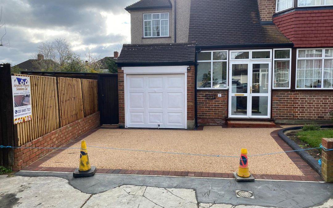
Resin bound surfacing has emerged as a premium architectural choice for modern vehicular entries due to its advanced material properties. This system utilizes a specialized two component aliphatic polyurethane resin matrix mixed thoroughly with thoroughly washed, kiln dried natural aggregates such as granite, quartz, or flint. The resulting slurry is troweled smooth onto a solid foundation to form a seamless, monolithic surface layer. Because the resin coats the stone particles without filling the microscopic voids between them, the cured surface features an incredibly high void ratio, allowing rainwater to pass straight down through the matrix instantly. Aliphatic resins must be utilized exclusively; unlike cheaper aromatic alternatives, aliphatic polymers are entirely stable under ultraviolet light, ensuring the driveway will not yellow, fade, or become brittle when exposed to decades of solar radiation.
For high load applications, sixty millimeter to eighty millimeter interlocking concrete blocks manufactured to comply with BS EN 1338 represent the industry benchmark. These blocks possess immense compressive strength and rely on joint friction to distribute heavy vehicular loads across a wide area. Stone Mastic Asphalt provides a highly cost effective, jointless finish that accommodates minor ground movements due to its flexible bitumen matrix. Reinforced imprinted concrete delivers an immovable, rigid slab system that completely eliminates the possibility of weed growth or block shifting, but it requires the precise installation of deep contraction joints to control thermal movement and prevent random structural cracking.
Advanced Hydrological Engineering and Statutory SUDS Compliance
Every modern front driveway installation must incorporate highly sophisticated water management systems designed to satisfy strict statutory environmental regulations. Under United Kingdom planning laws, any front garden modification that converts more than five square meters of natural grass into a non permeable surface must fully comply with Sustainable Drainage Systems, known as SUDS. The primary objective of these laws is to mitigate urban flood risks by legally preventing surface water run off from private residential properties from discharging directly into public highways and municipal storm sewers.
To achieve full SUDS compliance without requiring a formal, costly local planning application, property owners can choose between two main engineering approaches. The first approach is to construct a fully open, permeable driveway system utilizing resin bound aggregates or specialized porous block paving systems. The underlying bedding and foundation layers for these systems omit all standard fine dust particles, utilizing open graded aggregates such as 4/20 millimeter clean crushed granite instead. This structural design allows heavy rainfall to filter vertically straight through the driveway surface, passing into the subbase where it is temporarily stored before draining naturally into the subgrade soil without creating any surface run off.
The alternative approach allows for the use of dense, non permeable materials such as standard concrete blocks, tarmacadam, or imprinted concrete, provided the entire surface layout is engineered to capture all run off within the property line. The driveway must be constructed with a precise cross fall or longitudinal gradient of at least 1 in 80, directing all rainwater into high capacity linear drainage channels running along the property boundaries. These drainage channels must be piped directly into a professionally sized subterranean soakaway system located a minimum distance of five meters away from any building foundations. The soakaway must be constructed using high structural integrity attenuation cells wrapped in non woven geotextile fabric, ensuring it can collect and dissipate heavy storm water volumes safely within the domestic boundary.
Spatial Geometry: Optimizing Parking Configurations and Turning Radii
A professional driveway design must prioritize spatial ergonomics and geometric functionality alongside structural engineering. The layout configuration must accommodate the practical dimensions, turning capabilities, and safety requirements of modern motor vehicles, ensuring that drivers can enter, park, and exit the property safely and efficiently.
The minimum standard dimensions for a single residential parking bay are two point four meters in width by four point eight meters in length. However, to accommodate large modern sport utility vehicles, light commercial delivery vans, and multi generational family vehicles, a preferred bay size of two point seven meters by five point five meters is highly recommended. This expanded spacing ensures that vehicle doors can be opened fully without striking adjacent boundary walls, decorative planters, or other parked vehicles, protecting both the property and the automobiles from accidental damage.
When designing complex curved driveways, horse shoe entry loops, or integrated turning areas, engineers must carefully evaluate vehicle turning circles and swept path configurations. A standard passenger car requires a minimum turning radius of approximately five point five meters to clear a bend without its front or rear bumpers overhang the edge restraints. If the turning loop is constructed too tightly, drivers will constantly overrun the soft landscaping borders, which causes rapid structural collapse of the driveway edges and tracks mud across the paved surface. The entry throat connecting the driveway to the public highway must feature wide, sweeping flares to allow turning vehicles to clear the perimeter boundary walls without risking collision.
Rigid Perimeter Containment: The Mechanical Requirement for Concrete Haunching
A fundamental civil engineering law governing flexible driveway structures is that a pavement cannot maintain its alignment without permanent, rigid perimeter containment. When a heavy vehicle transitions onto a modular block or tarmacadam driveway, it generates substantial lateral thrust forces as the weight of the vehicle pushes downward and outward against the surface materials. If the outer edges of the driveway are not permanently locked in place, these lateral forces will rapidly push the perimeter elements outward.
This lateral spreading opens up the joints between block pavers, destroys the interlocking friction that holds the units together, allows water to easily wash away the underlying bedding sand, and results in rapid structural collapse along the driveway borders. To prevent this lateral failure, professional paving contractors teams must install robust, heavy duty concrete edge restraints around the entire perimeter before laying the primary surface materials. These restraints, whether utilizing industrial road curbs, high decorative granite sets, or natural clay headers, must be set permanently into a fresh concrete foundation bed that is a minimum of one hundred millimeters thick.
Crucially, the rear face of the perimeter curb must be supported by a substantial concrete haunch that extends halfway up the back of the block at a forty five degree angle. This structural concrete mass provides the mechanical resistance needed to counteract the immense lateral pressures exerted by turning vehicles, keeping the entire driveway structure permanently locked within its design matrix. For modern minimalist aesthetics where a visible concrete border is undesirable, hidden heavy duty steel L section restraints can be used, provided they are secured deep into the compacted aggregate base using high tensile anchoring pins driven at frequent, regular intervals.
A Step by Step Guide to a Complete Driveway Construction Sequence
Achieving an elite, structurally sound, and perfectly level driveway transformation requires strict adherence to a logical, highly controlled construction sequence performed with mechanical precision. The complete operational timeline is broken down into seven distinct construction phases.
Phase 1 involves detailed site surveying and level optimization. Engineers utilize advanced optical laser levels to calculate the exact slope lines needed to guarantee optimal water management away from the property foundations. Once the levels are marked, modern excavation machinery removes all old turf, concrete, and subsoil to the calculated design depths, and all waste material is cleared using licensed grab lorries.
Phase 2 focuses on subgrade stabilization and membrane deployment. The exposed subgrade soil is thoroughly compacted using industrial vibrating plates to eliminate any hidden soft spots. A high performance geotextile separation membrane is then spread across the entire excavated area. The membrane sheets must be overlapped by at least 300 millimeters at all internal joints and extended up the vertical sides of the excavation, creating a permanent barrier that isolates the aggregate foundation from the underlying soil profile.
Phase 3 is the installation of the MOT Type 1 aggregate sub base foundation. The stone is imported and spread evenly in thin layers, ensuring a uniform distribution of coarse and fine particles. A heavy mechanical vibrating plate compactor is then run over the aggregate multiple times until the base achieves maximum compaction density, leaving a firm surface that perfectly mirrors the final slope of the driveway.
Completing the Build: Screeding, Edge Setting, and Monolithic Compaction
Once the foundation is secure, Phase 4 moves into structural masonry and boundary retention works. Retaining walls, stepped entrances, and boundary pillars are built upon their concrete foundations, incorporating all necessary drainage pipes, gravel backfills, and weep holes to ensure long term stability.
Phase 5 is the application of the sharp bedding sand layer. Clean, washed sharp sand is spread across the sub base and meticulously leveled using heavy aluminum screeding bars riding on parallel height rails. This sand bed must be prepared to a uniform, uncompacted thickness of exactly 30 millimeters. This consistency ensures that when the paving blocks are consolidated later, they sink evenly without creating minor lips or tripping hazards.
Phase 6 is the precise hand placement of the selected paving units into the approved architectural pattern, such as a high strength 45 degree herringbone layout. Workers operate from the completed paving surface rather than stepping onto the freshly screeded sand bed. Individual blocks are pushed tightly against one another, and straight lines are constantly verified using taut alignment strings stretched across the site. Border blocks and complex angles around utilities are measured and neatly cut using water cooled diamond blade bench saws.
Phase 7 is the final jointing and structural consolidation phase. The entire paved surface is swept thoroughly to remove all surface debris, and clean, kiln dried jointing sand is spread across the pavement. A heavy plate compactor equipped with a protective polyurethane rubber under mat is then driven across the blocks in multiple directions. The vibration settles the individual blocks into the sharp sand bedding layer and forces the kiln dried sand tightly up into the vertical joints. The combination of sand friction and block placement transforms the independent units into a highly stable, monolithic structure capable of supporting immense vehicular loads.
Proactive Maintenance Systems for Preserving High Traffic Vehicular Assets
A professionally engineered driveway represents a significant financial investment that requires simple, proactive maintenance to preserve its structural integrity and aesthetic appearance over decades of intense exposure to vehicle use and changing weather conditions.
The primary operational challenge affecting external driveways is the accumulation of hydrocarbon stains, including engine oil drips, brake fluid spills, and power steering leaks. Because materials like standard concrete blocks and tarmacadam are semi porous, these automotive fluids will quickly soak deep into the surface matrix if left untreated, causing permanent dark discoloration and chemically breaking down the bitumen binder in asphalt surfaces. Property owners should apply specialized oil emulsifying detergents or absorbent compounds immediately to any fresh fluid spills, scrubbing the area with a stiff bristle brush and rinsing thoroughly with water to neutralize the chemicals before they can bond permanently with the stone.
When cleaning the driveway surface using high pressure jet washers, extreme caution must be exercised if the installation features traditional block paving. The intense force of a pressure washer will easily blast away the protective jointing sand from between the blocks, which immediately reduces the structural interlock of the pavement and allows the blocks to move independently under vehicle weight. If pressure washing is performed, the driveway must be allowed to dry completely for several days, and the joints must be immediately refilled with fresh kiln dried silica sand swept firmly into the gaps until completely packed to the surface level.
Applying a high grade acrylic, polyurethane, or fluoropolymer surface sealant is highly recommended to provide long term protection for vehicular driveways. Sealants form an invisible, oil resistant barrier across the surface layer, completely stopping fluid stains from penetrating the stone, inhibiting the growth of moss and weeds within the joint lines, and locking the joint sand in place to prevent erosion. Driveway sealants should be applied roughly twelve months after initial installation to allow any natural efflorescence to escape the concrete matrix naturally, and then refreshed every three to five years depending on the level of vehicle traffic wear.
Navigating Mid Sussex District Council Vehicle Crossing Frameworks
Every driveway project that requires driving a motor vehicle from a public highway across a public footpath into a private property boundary must fully comply with strict local government legislation. Constructing or modifying a front driveway access requires a formal application and approval for a legal vehicle crossing, universally known as a dropped kerb. Driving any motor vehicle over a standard public pedestrian pavement without an officially approved dropped kerb is a legal offense under Section 184 of the Highways Act 1980, and it exposes the property owner to full financial liability for any structural damage caused to underground public utility pipes, fiber optic cables, or water mains.
Property owners must submit a detailed application directly to the Mid Sussex District Council planning and highway departments before executing any boundary modifications. The council will evaluate the proposed site location against strict safety and traffic flow parameters, ensuring that the entry point provides clear visibility lines for passing pedestrians, features a minimum internal property depth to prevent parked vehicles from overhanging the public highway, and sits a safe distance away from busy road junctions, roundabouts, or public bus stops. Furthermore, since portions of the East Grinstead district fall within the High Weald Area of Outstanding Natural Beauty, distinct design constraints may apply, requiring the use of specific traditional materials that harmonize with the local historic environment. Homeowners can review the full statutory application guidelines and structural requirements by visiting the official Mid Sussex District Council portal.
The physical construction of the dropped kerb crossover within the public highway boundary cannot be performed by general landscape builders or the property owners themselves. The works must be executed exclusively by an approved principal contractor who holds full statutory accreditations under the New Roads and Street Works Act and carries extensive public liability insurance cover. The crossover must be constructed using specialized, heavy duty thick road base aggregates and distinct high density concrete curbs to withstand constant vehicular overruns without settling. For comprehensive safety parameters and strict operational guidelines during domestic construction projects, professionals and clients should regularly consult the Health and Safety Executive portal to ensure full site compliance.
Frequently Asked Questions Regarding Driveway Engineering
What is the primary technical cause of wheel rutting and sinking on block paved driveways?
Sunken wheel tracks and structural rutting along common driving lines are caused by inadequate sub base preparation or insufficient aggregate compaction density. If the aggregate foundation layer is installed too thin, features poor particle grading, or is not compressed thoroughly using a heavy mechanical compactor, the weight of passing vehicles will slowly force the aggregate particles closer together over time. This subterranean movement causes the upper bedding sand layer and the surface blocks to sink downward into the hollows, destroying the uniform surface alignment and creating deep channels that collect standing water.
Can a new resin bound driveway be successfully installed directly over an old concrete base?
Yes, a premium resin bound system can be installed over an existing concrete driveway, provided the old concrete slab is structurally sound, free of major cracks, and completely clean. The concrete base must be thoroughly inspected for any structural settlement or shifting, as any movement in the underlying concrete will quickly mirror upward, causing the resin surface layer to crack. The concrete must be thoroughly cleaned to remove all oil or grease residues, treated with a high strength polymer primer to ensure maximum adhesion, and drilled with frequent drainage holes if it lacks a proper fall to ensure rainwater can escape safely without trapping moisture beneath the resin matrix.
Why do oil leaks cause severe structural damage to standard tarmacadam driveways?
Tarmacadam and asphalt driveways utilize a flexible binder derived from crude oil bitumen to hold the stone aggregates together in a solid, resilient matrix. Because engine oil, diesel fuel, and brake fluids share a highly similar chemical structure to bitumen, they act as powerful solvents when spilled onto an asphalt surface. The spilled automotive fluids quickly dissolve the chemical bonds within the bitumen binder, causing the aggregate stones to separate and crumble away from the surface layer. This process, known as raveling, creates deep structural holes and loose gravel patches that require immediate cutting out and professional patching to repair.
What specific thickness of block paving is required to support light commercial delivery vehicles?
For standard domestic driveways intended exclusively for standard family passenger cars and small sport utility vehicles, a block paving thickness of fifty millimeters is generally sufficient, provided the aggregate sub base is engineered correctly. However, for driveways that receive regular traffic from light commercial vehicles, heavy home delivery vans, grocery trucks, or large motorhomes, a minimum block thickness of sixty millimeters is highly recommended. For heavy commercial access areas or shared industrial entries, eighty millimeter thick heavy duty interlocking blocks must be utilized to resist the intense loading and rotational forces generated by multi axle vehicles.
How far away from mature trees should a new driveway foundation be excavated?
To protect both the long term structural health of the driveway and the biological viability of the local environment, excavation work should respect the Root Protection Area of mature trees, in strict compliance with British Standard BS 5837. Digging deep foundation trenches too close to a mature tree can sever vital structural anchor roots, destabilizing the tree and causing rapid die back. Furthermore, as the remaining roots grow and expand over time, they can exert immense upward pressure beneath the driveway foundation, easily cracking heavy concrete slabs and lifting block pavers out of alignment. If a driveway must pass within a tree protection zone, specialized no dig three dimensional cellular confinement systems must be utilized to spread vehicle weights without compressing the underlying root structures.
